You’ve sized the electrolyzer stack. You’ve secured the grid connection. Now comes the part that delays more green hydrogen projects than any other: power supply integration.
PEM or alkaline? 500KW-5MW or even higher power ratings? Air‑cooled or liquid‑cooled? The answers depend not just on nameplate power, but on your plant’s capacity factor, ambient conditions, and grid code.
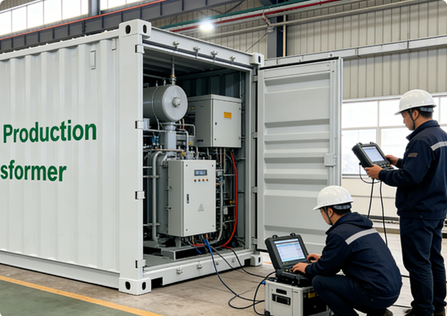
Over the past four years, the application engineering team at Hygen Power has supported over 20 electrolysis projects — from containerized demo units to multi‑MW hydrogen hubs. This guide consolidates what we learned. It is not a generic rectifier theory. It is a step‑by‑step integration roadmap with decisions that directly affect your timeline, opex, and reliability.
Step 0: Know Your Electrolyzer First – PEM vs. Alkaline
Before touching any cable, understand your stack’s electrical personality.
| Parameter | PEM Electrolyzer | Alkaline (AWE) Electrolyzer |
|---|---|---|
| DC voltage range | 150–450 V typical | 300–800 V typical |
| Current ripple sensitivity | High (>3% ripple degrades membrane) | Moderate (5–8% acceptable) |
| Dynamic response | Fast (<100 ms) | Slow (seconds) |
| Auxiliary power needs | Deionized water loop, cooling | Lye circulation, cooling |
If you are integrating a PEM system, your IGBT power stage needs low output ripple and fast current control. For alkaline, the priority shifts to wide voltage range and overload capability for cold starts.
This difference will guide every choice below. Review electrolyzer‑specific power interface requirements before finalizing your converter topology.
Step 1: Site Survey and AC Grid Readiness
Most green hydrogen projects are built on industrial land with limited grid capacity. Verify three things:
-
Available fault current (must be within IGBT module’s rating)
-
Grid impedance (affects commutation notches and harmonic injection)
-
Existing power factor correction capacitors (can interact with your rectifier’s front‑end filter)
For weak grids (short‑circuit ratio < 10), you may need an active front end instead of a passive rectifier. For plants requiring low‑voltage ride‑through (LVRT) per Rule 21 or VDE‑AR‑N 4120, the IGBT power supply must include grid‑forming control logic. Do not assume a standard industrial drive will pass these tests.
Step 2: Choose Your Cooling Architecture – Decision Tree
An IGBT‑based rectifier at 2 MW and 97% efficiency still rejects 60 kW of heat. How you remove that heat determines your plant’s uptime.
Decision tree:
-
Annual runtime < 2000 hours (intermittent, backup) → Forced air cooling may work. Budget for monthly filter cleaning.
-
Annual runtime 2000–6000 hours → Liquid‑cooled strongly preferred. The upfront cost pays back in avoided downtime.
-
Annual runtime > 6000 hours (continuous, baseload) → Liquid‑cooled mandatory. Air cooling will derate above 35 °C ambient.
If you choose liquid cooling, size the dry cooler or chiller for 110% of the rectifier’s rated losses. Use deionized water with conductivity < 1 µS/cm. Monitor coolant flow with a redundant pressure switch – loss of flow destroys IGBT modules in under 30 seconds.
Step 3: AC Input Cabling and Protection
Use copper cables rated for 125% of input current. For IGBT converters, the AC side sees non‑sinusoidal current with high di/dt. Standard thermal‑magnetic breakers may nuisance trip. Install semiconductor fuses (aR or gR type) instead.
Critical missing component: an LCL filter or at least 3% line reactor. Without it, switching harmonics back‑feed into your facility grid, resetting PLCs and interfering with gas analyzers. Many project delays trace back to a missing line reactor.
Step 4: DC Bus Bar Connection – Where Field Failures Happen
High current (e.g., 4000 A at 500 V DC) creates strong magnetic forces. Follow three rules:
-
Equal length for parallel IGBT half‑bridges to ensure current sharing.
-
Correct torque – under‑torquing creates resistive hotspots; over‑torquing cracks insulators.
-
Insulated sleeves for finger‑safe maintenance.
Polarity is critical. PEM electrolyzers require positive DC to the anode. A reverse polarity event destroys catalyst layers instantly. Double‑check with a multimeter before energizing.
If you are connecting to a specific electrolyzer model (e.g., Nel, ITM, Sunfire, John Cockerill), bus bar hole patterns and offset dimensions vary. Pre‑fabricated adapter kits save days of onsite fabrication. Check available DC interface adapters for common electrolyzer brands before ordering cables.
Step 5: Control Wiring and Stack Interlocks
Your IGBT power supply must talk to the electrolyzer’s PLC or DCS. At minimum, implement:
-
4–20 mA setpoint from electrolyzer controller to power supply
-
0–10 V feedback of actual DC voltage
-
Hardwired emergency stop (redundant, not over the fieldbus)
Most important interlock: A “stack ready” contact that closes only when electrolyzer pressure, temperature, and water flow are within safe ranges. The power supply should not enable DC output without this signal. This simple failsafe prevents membrane dry‑out and thermal runaway.
Step 6: Pre‑Commissioning Insulation Tests
Before applying any power, perform these megger tests:
| Test Point | Voltage | Minimum acceptable |
|---|---|---|
| AC phase‑to‑phase & phase‑to‑ground | 1 kV DC | 10 MΩ |
| DC positive‑to‑negative (bus bars disconnected from stack) | 500 V DC | 5 MΩ |
| DC terminals‑to‑ground | 1 kV DC | 20 MΩ |
Also, verify the pre‑charge circuit slowly charges the DC link capacitors. A direct connection without pre‑charge will weld contactors or blow fuses.
Step 7: Low‑Power Test with Dummy Load
Never connect your expensive electrolyzer stack for the first test. Use a resistive dummy load (water bath resistor or load bank) at 10–25% of rated current. Verify:
-
Current control stability (no oscillation)
-
DC voltage ripple (should be <3% for PEM, <5% for alkaline)
-
Thermal balance (all IGBT modules within 5 °C of each other)
If ripple exceeds these values, revisit the DC link capacitor bank or adjust the IGBT switching frequency.
Step 8: Site Acceptance Test with Electrolyzer
Ramp current slowly: 10% → 25% → 50% → 75% → 100% in 30‑minute steps. At each step, record:
-
DC voltage and current → calculate power
-
AC input power → calculate efficiency
-
Coolant inlet/outlet temperature delta
-
Total harmonic distortion (THD should be <5% at full load)
If efficiency falls below 94% or THD exceeds 8%, check for phase current imbalance or grid voltage distortion.
Common Integration Mistakes (And How to Avoid Them)
| Mistake | Consequence | Prevention |
|---|---|---|
| Ignoring cooling derating for ambient >40 °C | IGBT overtemperature shutdown at 70% load | Derate by 1.5% per °C above 40 °C, or switch to liquid cooling |
| Sharing ground between AC and DC | Ground loop currents corrupt 4‑20 mA signals | Use separate isolated grounds, tie only at single point |
| No DC pre‑charge circuit verified | Inrush current melts bus bars | Always test pre‑charge before main contactor closes |
| Using standard slow‑blow fuses | Fuse fails to clear a semiconductor short, causing an explosion | Use aR (ultra‑fast) semiconductor fuses only |
For projects requiring utility grid compliance, the integration becomes more complex. Download the grid‑code compliance checklist for electrolysis rectifiers – it covers LVRT, reactive power capability, and harmonic limits per IEEE 519 and IEC 61000‑3‑12.
Beyond Integration: What to Monitor After Commissioning
Two metrics predict IGBT power supply health:
-
DC link capacitance degradation – measure ripple voltage at no load every 6 months. A 20% increase suggests capacitor replacement.
-
IGBT saturation voltage (Vce(sat)) – logged via on‑board temperature sensors. A rising trend indicates bond wire fatigue.
Track these in your SCADA or a simple spreadsheet. Replacing an IGBT module proactively costs 10% of an emergency replacement that shuts down hydrogen production for two weeks.
Why Pre‑Engineered Solutions Reduce Project Risk
Many of the integration steps above – cooling sizing, LCL filter tuning, grid code logic, and stack‑specific bus bar adapters – can be pre‑solved.
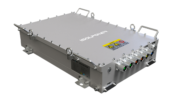
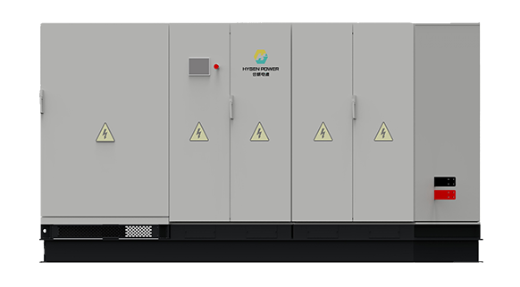
Instead of building these from discrete components, an increasing number of integrators choose a pre‑engineered IGBT power platform that arrives with:
-
Factory‑tuned LCL filter and pre‑charge circuit
-
Liquid cooling manifold with flow and temperature sensors
-
Grid‑forming control software pre‑loaded
-
Stack‑specific DC interface (adapter bus bars and control mapping)
If you are finalizing a BOM for a 500 kW–3 MW electrolysis plant and want to avoid the integration traps in Steps 4, 5, and 7, explore Hygen Power’s pre‑assembled electrolysis DC power supplies – each is factory‑tested with a simulated electrolyzer load and ships with a one‑page integration checklist your electrical contractor can follow in hours, not weeks.
Final Check
A well‑integrated IGBT power supply should be boring. It sits in a corner, converts AC to DC quietly, and produces hydrogen predictably for years.
By following these eight steps – starting with electrolyzer type, prioritizing cooling for your runtime, testing with a dummy load, and monitoring continuously – you avoid the common pitfalls that turn power electronics into a project bottleneck.
If you are currently sourcing power conversion for a green hydrogen project and would like a 15‑minute application review with an engineer who has done this for PEM and alkaline stacks, contact Hygen Power’s technical sales team. Ask for the pre‑commissioning checklist – it is free and covers the one measurement most integrators forget.